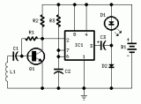
A while ago I got an email asking for the schematic of a circuit to detect cut phone lines. It didn't take me long to find this circuit in Electronics Now. When the circuit detects that a phone line has been cut, it activates a MOSFET which can be used to drive a relay, motor, etc. It can also be connected to a security system.
Parts
R1, R2, R3 22 Meg 1/4 W Resistor
R4 2.2 Meg 1/4 W Resistor
C1 0.47uF 250V Mylar Capicitor
Q1 2N3904 Transistor or 2N2222
Q2 2N3906 Transistor
Q3 IRF510 Power MOSFET
D1 1N914 Diode
Load See "Notes"
MISC Wire, Phone Connectors, Circiut Board
Notes
1. The "Load" can be a relay, lamp, motor, etc. The circuit can also be connected to a security system to sound an alarm in case the phone line is cut.
2. If the circuit is connected to a security system or other circuit, both circuits must be electrically isolated from each other using an opto-isolator, relay, etc. This also means that the Cut Phone Line Detector must be powered by a seperate 9V supply.
Author:
Email:
Website: http://www.aaroncake.net

 Audio
Audio


