 Audio
Audio 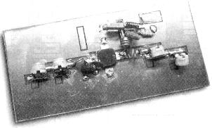
A amplifier of force RF for the FM, is always essential for the amateur that wants it strengthens some small transmitter, that likely already it has manufactured or has been supplied ready. The present circuit can give 50-60W RF force of expense, with control smaller than 15-20W in the region of frequencies of FM, that is to say in the 88-108MHZ. Transistor that we selected for this manufacture is the BLY90, that has gain 5dB.
Circuit diagram

Description
As it appears in the analytic drawing (image 1) the amplifier is manufactured with transistor TR1, type BLY90 of Philips. The transistor this is specifically drawn for operation in frequencies up to 175MHZ, with very good results of linearity and record of force. In his technical' characteristics they are included the tendency of operation in the 12V the current of collector in the gain expense in the 5dB (measured in order C) and force of entry in the 16W. Variable capacitors C1, C2, with inductor L1, constitute the circuit of co-ordination, that adapts the exit of our transmitter in amplifier RF. This circuit has been calculated suitably, so that it covers all band the FM with the biggest possible output.
Inductor RFC1 polarized the transistor, so as to it works in order C, that is to say with the biggest output. Inductor L2 in the collector of TR1, constitutes the charge of amplifier, while RFC2 prevents the RF signals leak in the line of catering. Capacitor C2 and resistance R1, protect the circuit from auto polarization. The coordinated circuit of expense that is constituted by inductor L2 and variable capacitors C3, C4, adapts the exit of amplifier RF with the next stage, which can be constituted from some amplifier RF of high force (> 300W) or a aerial. This circuit can be supplied with 12V f.e from the battery of one automotive, so that it renders the system emitter portable. Thus, easily it can be moved in points with bigger altitude, in order that from there are achieved radio transmissions, something that was also got used in the past by romantic amateur of radio band.
The manufacture
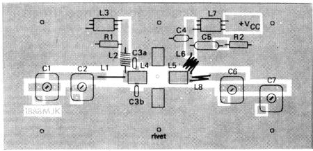
The manufacture of amplifier, is very simple and easy, it is enough to look the images 3 and 2 that portray pcb the amplifier and the placement of materials in this. Puncture the point pcb, that pass the nutshell of TR1. Sticks the capacitors, variable, the resistance, RF tsok and the inductors. Finally you stick TR1, being careful not overheating at the welding and bend the pins his. Clean finally pcb from the residues of iron. Make a very careful control for by any chance errors, omissions, short-circuits, chills you stick also anything other that could you make think that will not work the amplifier.
If all they are it includes, you connect the exit of your transmitter (15-20W) in input the amplifier. The exit of amplifier him you will connect in some charge (dummy load) or in the aerial, through bridge stagnant waves. Supply with tendency 11-15V your amplifier (power supply it should gives current 4-5A). Regulate the 4 variable C1-C4, until you take the biggest force of expense. The amplifier is ready.
Note:
TR1 needs a wiper of dimensions 5x10cm for trouble free operation. This wiper in TR1, without insulator, after his central screw has electric isolation from remainder pins.
Parts
C1-C4 = 10-80pF
C5 = 10nF
C6 = 1000pF
C7 = 100nF
C8 = 2200mF/35V
L1 = 1 coils of diameter of 10mms, 1mm
L2 = 7 coils of diameter of 10mms, 0,8mms
L3 = 3 coils of diameter of 10mms, 1mm
TR1 = BLY90

The printed circuit of amplifier of is double aspect but the down aspect is all coper
Author: Technical Election
Email: steve_filianos@hotmail.com
Website: http://www.techline.gr/


