 Audio
Audio 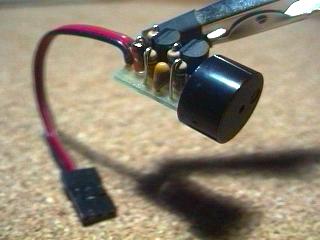
Here is another equally cool low voltage alarm circuit for your glider receiver battery that I've shamelessly stolen from George Steiner's book "A to Z--Radio Control Electronic Journal" (see below). I've modified it to use with small battery packs in R/C gliders. This design has a trigger voltage at about 4.3 volts, and it draws 1mA or less when quiet and about 4mA when buzzing. This can be constructed from parts fromt Radio Shack, though you may need to order a few through them.
The voltage of a receiver system is punctuated by low-voltage spikes every time the servo motors spin up, since the servos draw more than the battery can deliver. With large receiver battery packs, this is not as much of an issue, and it may not be noticeable. However with 270mA and smaller battery packs, particularly with more than two servos, low voltage alarms can chirp constantly, every time a servo moves. The challenge is to design in a little slack or delay, just enough so that you are not annoyed by constant chirping, but not too much so that the chirps can give you a warning before the battery is completely exhausted. Here, this "hysteresis" is adjusted with the capacitor. For large packs (600mA and above), no capacitor is probably needed, although I've been using a 1uF capacitor on my open class ship with 6 servos and a 600mA battery. For 270 mA and two servos, I'd suggest trying a 1uF capacitor. For 150mA or less, a 2.2uF capacitor works well. If you want to know only when the battery has finally reached the trigger voltage, try a 5uF (or 4.7uF) capacitor. The actual type of capacitor is not critical, but tantalum capacitors are physically smaller. If you want to worry about the polarity of the capacitor, the negative side should be directed toward the negative pole of the battery, but at these relatively low voltages compared to the capacitor rating, the polarity probably does not matter.
This circuit is set up for a four cell receiver battery pack at a trigger voltage of about 4.3 volts (about 1.1volts/cell). You can adjust R1 (here a 3.3k resistor) to change the trigger voltage of the circuit. For example, for a 5 cell pack, to change the trigger voltage to 5.5 volts, change R1 to 2.2k. For a three cell pack, to change the trigger voltage to 3.3 volts, change R1 to 6.8 k (or use two 3.3k resistors in parallel by soldering a resistor in each hole and twisting together the top leads). Because of slight variability in tolerances of the componants, you should check this little device with a variable power source and a voltmeter to confirm its trigger point. Alternately, use your digital voltmeter or expanded scale voltmeter to calibrate its chirp pattern by measuring the voltage of the onboard battery pack intermittently as you fly.
Make sure the band on the Zener diode is toward the "+" side (toward R1). Solder a battery connector or servo connector to the board with positive and negative as shown, and plug the connector into an unused slot in your receiver.
Circuit diagram


Radio Shack parts: Here again, you can use smaller rated resistors if you can get them--1/8 watt or less is fine. Tantalum capacitors are physically smaller, but any composition will work.
273-074 Miniature Piezo Buzzer, 12v, PC board mount
271-312 1/4 watt 5% carbon film resistors, 500 pieces (Take the plunge!)
276-1604 Package of 15 PNP small signal 2N3906-type transistors. Could use instead 276-2016 $0.59 2N3904 PNP transistors
RSU 11673505 3.3v Zener diode (not on shelf--need to order 1-800-THE-SHACK)
272-1434 1uf tantalum capacitor (see above for choice of capacitor)
RSU 11295888 2.2uF tantalum capacitor (not on shelf--need to order)
272-1024 4.7uF radial-lead electrolytic capacitor
Digikey (1-800-344-4539) part numbers: Digikey does sell the peizo buzzers, but they are much more expensive than those at Radio Shack and are larger as well.
2N3906-ND PNP general purpose amp/switch transistor
1N5226BMSCT-ND 3.3v Zener diode 500mA
3.3KEBK-ND 1/8 watt resistors
4.7KEBK-ND 1/8 watt resistors
10KEBK-ND 1/8 watt resistors
P2105-ND 1.0uF Tantalum capacitor 16volt
P2022-ND 2.2uF Tantalum capacitor 10volt
P2024-ND 4.7uF Tantalum capacitor 10 volt
FP012C-5-ND 3M clear 0.5" heat shrink tubing, 5 feet
George Steiner's book, crammed with cool R/C radio info, can be had for $19.95 postage paid from the following:
GSP AZ Journal
2238 Rogue River Drive
Sacramento CA 95826
phone: 916-362-1962
Author: Rob Crockett 10/99
Email:
Website: http://www.electronics-lab.com


