Linear scale Small size
40 to 208 beats per minute
Parts:
P1 100K Linear Potentiometer
R1 10K 1/2W Trimmer Cermet
R2 10K 1/4W Resistor
R3 330K 1/4W Resistor
R4 50K 1/2W Trimmer Cermet
R5 100K 1/4W Resistor
R6,R7 1K 1/4W Resistor
C1 1µF 63V Polyester Capacitor
C2 10nF 63V Polyester Capacitor
C3 47µF 25V Electrolytic Capacitor
IC1 NE555 General purpose timer IC
Q1,Q2 BC560 45V 100mA Low noise High gain PNP Transistors
Q3 ZTX753 100V 2A PNP Transistor
SW1 SPST Switch (Ganged with P1)
SPK 8 Ohm 40mm. Loudspeaker
B1 12V Battery (MN21, GP23A or VR22 type)
Notes:
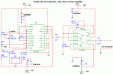
Q1 & Q2 provide linear frequency operation of IC1 following P1 resistance variation.
Q3 was added in order to obtain a louder click, similar to clockwork metronomes.
12V micro battery was used to obtain more output power and more compactness.
Rotate P1 fully towards R2, then set R1 to obtain 40 beats per minute (compare with another metronome).
Rotate P1 fully towards R3, then set R4 to obtain 208 beats per minute.
Finally mark the entire scale with the usual metronome steps as following:
40 - 42 - 44 - 46 - 48 - 50 - 52 - 54 - 58 - 60 - 63 - 66 - 69 - 72 - 76 - 80 - 84 - 88 - 92 - 96 - 100 - 104 - 108 - 112 - 116 - 120 - 126 - 132 - 138 - 144 - 152 - 160 - 168 - 176 - 184 - 192 - 200 - 208.
Author: RED Free Circuit Designs
Email:
Website: http://www.redcircuits.com

 Audio
Audio


