 Audio
AudioMe and a friend are both trying to build a millipede. Because of obvious reasons, the millipede is NOT going to have 1000 feet!!! Instead, it's going to have 16 pager motors as feet. It will also have 3 MicroMotors to ''bend'' towards light, and a backup sensor.
FEATURES:
16 PagerMotors as feet
3 MicroMotors to seek light
PhotoTrophic
Obstacle avoidance
Looks Cool!!!
MECHANICS:

Millipede is divided in four segments. Each segment (except the first one) is glued to a MicroMotor turned upside-down. The motor shaft is then glued to the next segment. Each segment can rotate left/right and has 2 PagerMotors on each side. This way, the millipede should turn towards the most lighted area. I've calculated that the waist motors should turn only 30o-45o every second or so. This means that I will need the motors to be 7-15 rpm. Candidates for this job can be the Lego MicroMotor (http://costaricabeam.solarbotics.net/Info/Lego%20MicroMotor.htm), Solarbotics GM or BabyGM (unless I can get some MU915L Escaps!!!).
Weigth was a major concern since the whole bot was impulsed by pagermotors. The waist motors should weigth no more than 70g and the body (including electronics) is about <100g. Actually, it seems that 16 pagermotors are more than enough to move the bot!!!
ELECTRONICS:
Circuit diagram
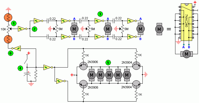
I made up this circuit, as this is my first ''big'' BEAM creation I have no idea if it works properly. The upper 3 Ms are the Lego MicroMotors and the lower Ms should be the 16 PagerMotors. On the right, you can see the MicroMotors driver.
Here is the explanation:
1 This is the voltage divider. It divides voltage depending on which side is more iluminated, then, the schmitt changes the signal from a wave to a straight pulse.
2 The (usual) Nv only works when the input receives a HIGH, and that is the job of the schmitts. If the first schmitt outputs a HIGH the the lower strip of Nvs will work, the upper strip should stay calm because the second schmitt inverts the signal to a LOW. Thanks Math!!!
3 I can now be sure that there won't be 2 pulses on a same motor, and that when the first motor turns left (or right) the next one will also turn that same way, and the next and the next.... Only the first motor is affected by light, the others follow (in a wave pattern) the one before themselves. Since the millipede is moving forward while all this happens, a nice wave should appear when the bot has locked his path towards the light source.
4 This is the backup switch. When the bot bumps into something like... Hmm....anything, the cap is discharged trough the right schmitt. The (now LOW) output of the schmitt will reverse the PagerMotors, thus, reversing the whole bot.
5 This is the PagerMotors driver. I took the 4 transistor circuit design and modified it to be used with only one input signal. I know I won't be able to drive the 16 motors with 2N390X transistors, I used them in the schematic only because I need to find more powerful ones. Probably FETs?
6 As an extra (Yupeee), when the bot reverses it also makes the ''spinal column'' think that light is fully comming only from one direction. Because of this, when the millipede reverses, it also turns to one side all the body.
I still need to order the components (Let's just say there are not many 74**14s or 240s in Costa Rica), so the final version may be different than the drawings. I'm also thinking about using the Baby GMs that Solarbotics sell instead of the Lego MicroMotors. If you can help me with anything about the schematic, just email me.
Author: Juan A Cubillo
Email: jacubilloro2000@yahoo.com
Website: http://www.electronics-lab.com


